Adding a Skybox to RenderMonkey

Yesterday I wrote a tutorial about the basics of RenderMonkey. This time I’ll be showing how to replace the solid colored background that RenderMonkey uses to clear the screen, with a skybox. I expect you to have read and tried that tutorial already, and know your way around HLSL and how to create a skybox outside the context of RenderMonkey. There are many resources available on the web about how to implement skyboxes (such as this). By the way, my implementation is based on Riemer Grootjans’ book XNA 3.0 Game Programming Recipes , which is quite a useful book covering a lot of different topics.
Introduction
On the day I started writing my first shaders on RenderMonkey, I had to figure out how to add a skybox to my scene so that I could properly test effects such as environment mapping. I searched around RenderMonkey’s interface but did not find any built-in way of rendering a skybox, so I ended up writing it on my own. I thought there could be a more intuitive way of doing this, so I figure it might be of some worth sharing my experience here. But if there is indeed an easier way to accomplish this, please let me know!
The trick to rendering the skybox was to add a second shader pass to the effect, and using the first one for the skybox while the second one is used for the model. The implementation I’ll be showing here works by rendering a simple texture mapped cube model (generated procedurally by RenderMonkey) which is always centered around the camera. This way, no matter where your camera is, the skybox will always look like it’s staying far away from the it. In order to be able to render the cube from inside out, I had modify the graphic card’s render state and invert the culling order, and I also had to disable writing to the Z-buffer while rendering the skybox, so that it didn’t interfer later with my scene on the second pass. As for the texturing of the skybox, I used one of the default cubemaps and the texCUBE HLSL intrinsic do to all the work. Well, let’s get started!
Starting the Effect
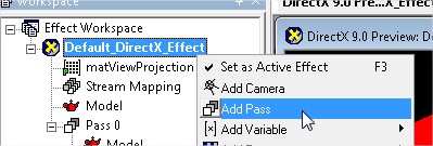
The first step is to create a new DirectX effect on your workspace and add a second pass to it by right-clicking on the effect and choose “Add Pass”:
Your workspace should look like this afterwards:
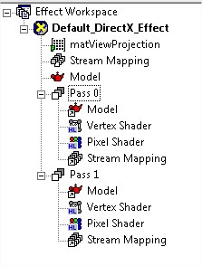
From now on you’ll be working mostly on the first pass (Pass 0) to set up that skybox. You’ll need to create a cube model, prepare some variables and a cubemap texture for the shader, write the shader itself and configure the graphic card’s render state properly. But don’t worry, I’ll guide you step by step.
Creating the Cube
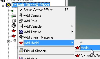
To create the cube model that will be used as a skybox, right-click on your effect and add a new model, but don’t choose any model from the list. Instead click on the default model which is on top of the list. Rename it to “Box” if you want so that you don’t confuse it with the existing model.
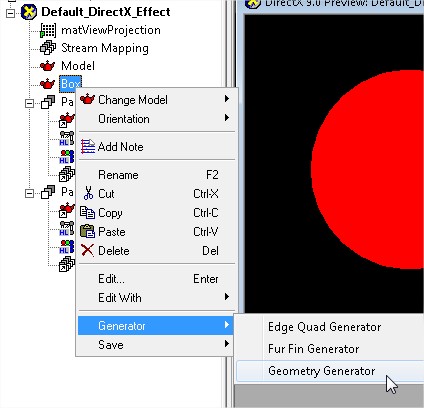
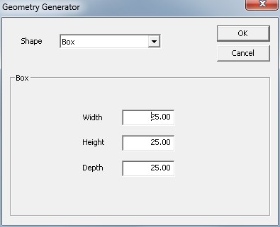
Now right-click on your new model, and select “Geometry Generator” under the “Generator” menu option. This will fill your model with data that is procedurally generated by RenderMonkey based on your choices:
On the dialog that pops up, create a box of arbitrary size. I created a 25x25x25 box which worked fine for me, because depending on your near and far planes are configured, choosing a box that is too small or too large may cause problems:
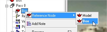
And before we forget, head inside your pass 0, and right-clicking on the model Reference Node there, assign it to your newly created box, because it’s probably still be pointing at your first model:
Creating Variables
The skybox shader I’ll be showing below makes use of three global variables: the position of the camera, the view-projection matrix and the cubemap texture used for the sky:
float4 ViewPosition;
float4x4 ViewProjection;
sampler Texture;
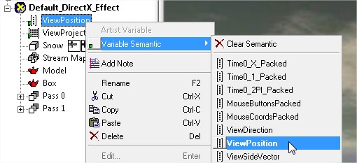
So go ahead and create each of these variables as explained on the previous tutorial, remembering to choose the appropriate data types and semantics. The ViewProjection matrix should already be created for you by default, I simply renamed it because I don’t like the default notation. As for the ViewPosition, can find it under the Float predefined variables:
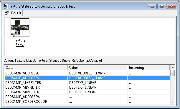
For the texture, use the specific Cubemap option to load it:

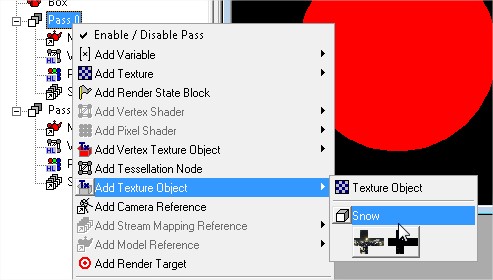
And don’t forget to also add a Texture Object called “Texture” to your pass 0, linked to the cubemap you just created:
Optionally, you can configure your texture object to use a better filtering scheme:
Adding the Code
Now it’s time to add the vertex and pixel shader code. You can find it ready below, so simply copy it into the vertex shader and pixel shader sections of pass 0. The code is commented to explain what it’s doing, but if you have any questions let me know!
The vertex shader:
float4 ViewPosition;
float4x4 ViewProjection;

struct VS_INPUT
{
    float4 position : POSITION0;
};

struct VS_OUTPUT
{
    float4 position : POSITION0;
    float3 position3D : TEXCOORD0;
};

// Constructs a translation matrix
float4x4 translation(float3 position)
{
    return float4x4(
        float4(1,0,0,0),
        float4(0,1,0,0),
        float4(0,0,1,0),
        float4(position.xyz, 1)
    );
}

VS_OUTPUT vs_main(VS_INPUT input)
{
    VS_OUTPUT output;

    // Create a world matrix that translates the skybox to the camera position
    float4x4 world = translation(ViewPosition.xyz);

    // Combine it with the existing view projection matrix
    float4x4 WorldViewProjection = mul(world, ViewProjection);

    // Transform your vertex into place
    output.position = mul(input.position, WorldViewProjection);

    // Save the original vertex position in model space
    // Since the cube model is centered around the origin, you can use these
    // vertex positions directly as directions for your cubemap :)
    output.position3D = input.position;

    return output;
}
The pixel shader:
sampler Texture;

struct VS_OUTPUT
{
    float4 position : POSITION0;
    float3 position3D : TEXCOORD0;
};

float4 ps_main(VS_OUTPUT input) : COLOR0
{
    // Use the original vertex position to sample the texture cube
    return texCUBE(Texture, input.position3D);
}
Configure Render States
You probably still can’t see anything, but the shader should already compile without errors. The reason you can’t see anything is because you’re seeing the cube model from inside out, and since its faces are facing the wrong direction they aren’t rendered. Let’s correct that now by changing the culling mode on our graphics card. Another thing we need to do is disable writing to the z-buffer because we want the sky to always appear last in the scene.
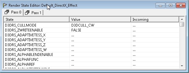
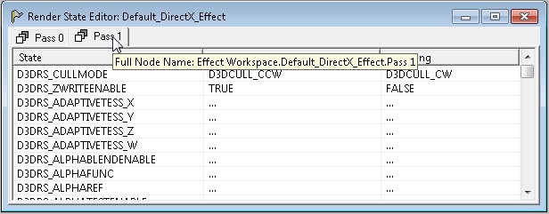
To add these changes, simply right-click on pass 0 and select “Add Render State Block” from the list. Now repeat the same thing on pass 1 because you’ll want to undo your changes there before rendering your model. Match your settings to the ones on the pictures below.
Pass 0 Render State Options:
Pass 1 Render State Options:
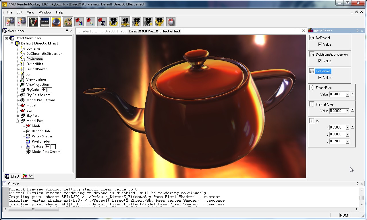
Conclusion
And that’s it! Now you can change over to pass 1 and write another shader there, because the skybox will still be displayed on the background, and react correctly to the camera. Here’s the result:
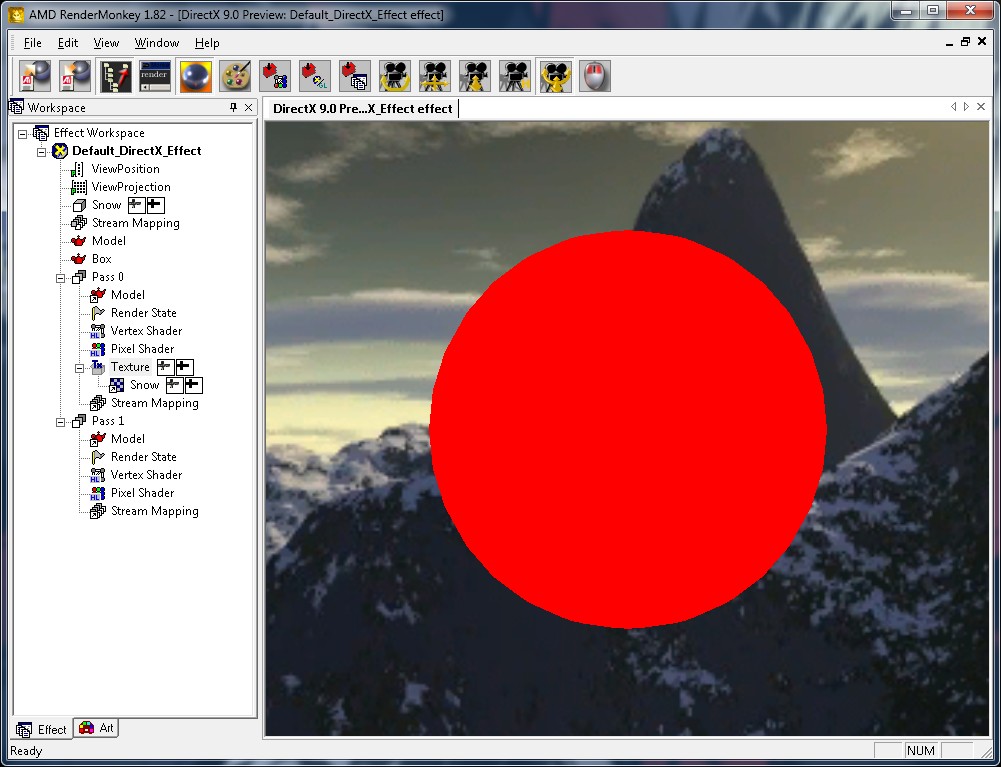
And having a proper skybox in place opens the door to testing many different effects involving reflection and refraction such as this:
Just one final tip: by default, your pass 1 is referencing the same Stream Mapping structure as pass 0. If you need different sets of data for both passes, just create a new Stream Mapping object on your effect, and using the right mouse button, change the reference on pass 1 to your new instance.
That’s all for today, I hope you enjoyed the article.